OverviewL
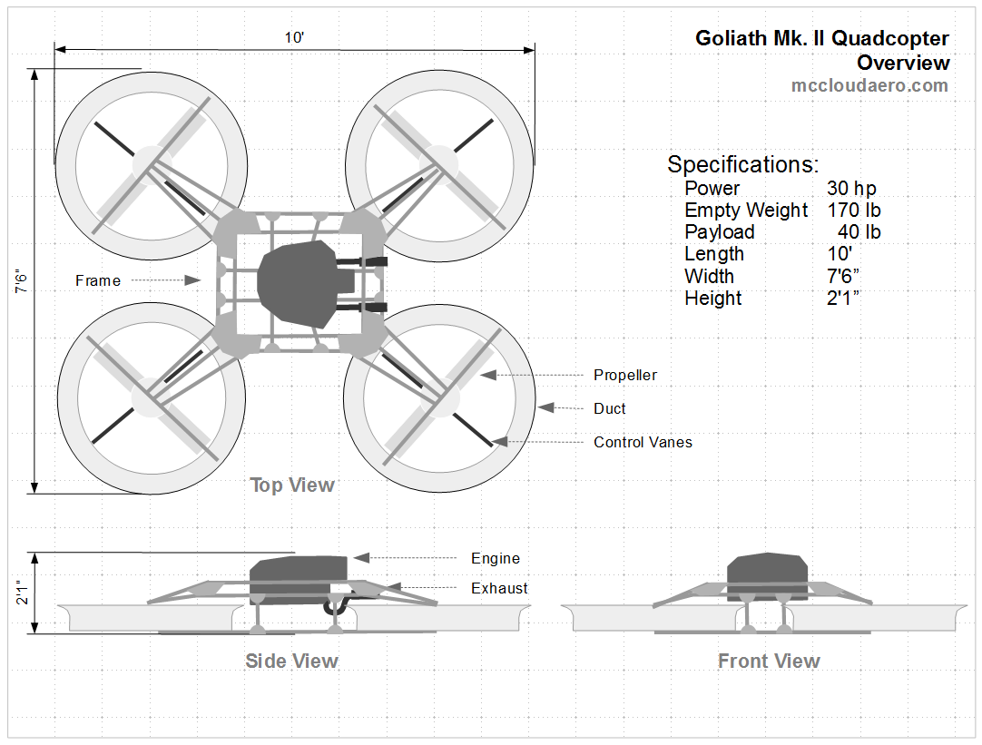
Goliath is a prototype vehicle for developing large scale quadcopters. The design is based on a single central gas engine with a belt drive providing power to the four propellers. Control is done using control vanes placed under the propellers. Each propeller is enclosed within a duct that protects the rotors and contributes to the lift. Goliath itself will be open source with the creative commons license, and whenever possible open source components were used. It's currently a work in progress, and even when completed it's intended as a starting point for future vehicles.
THP Semi-Finalist Video
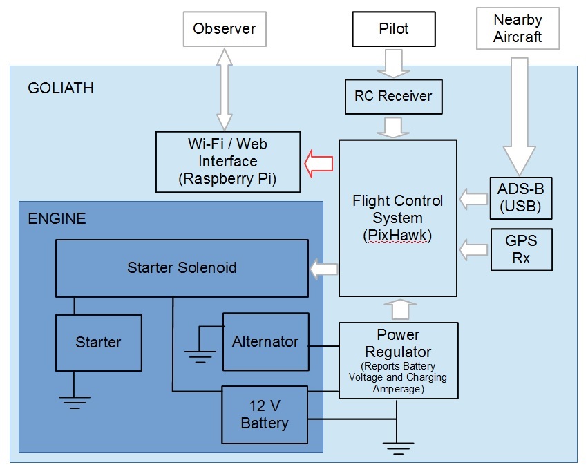
Flight control will be performed using the Pixhawk controller running a modified version of the Ardupilot flight software. Modifications to the Ardupilot software are needed to work with Goliath's unique control system. Both the Pixhawk and Ardupilot are open source. The modifications made will be open source as well. A USB radio receiver will be attached to the flight controller and setup to receive ADS-B signals. These signals will allow the operator to be aware of other aircraft operating in the area.Additionally Goliath will have a WiFi interface allowing the public to interact and connect with Goliath. Data and Video Feeds will be available and observers can notify the operator of potential issues.
Engine
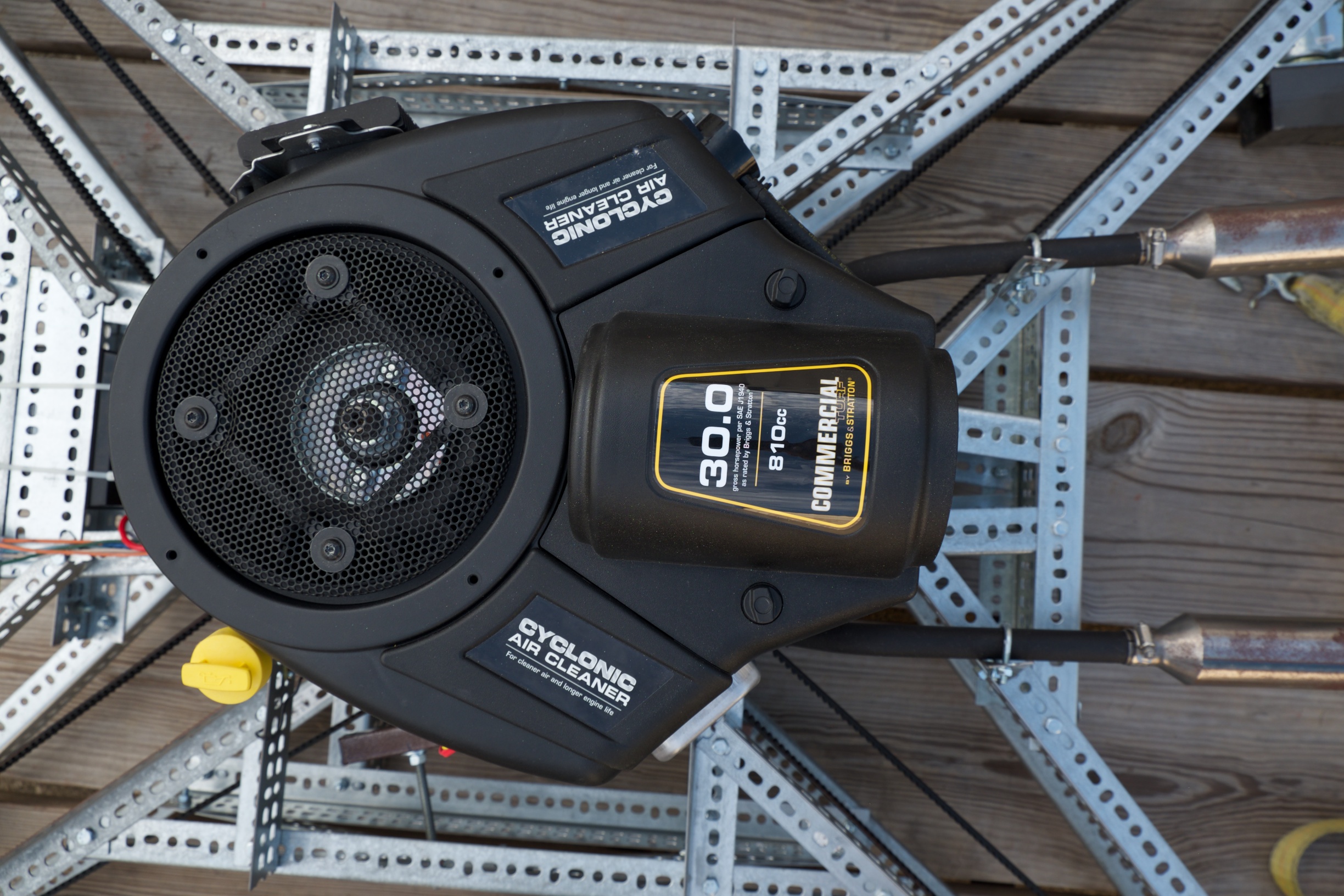
An electric powered design would have been the most straightforward approach. Electric motors are more efficient than gas, but the power density of gasoline is much greater than today's batteries. So until battery technology improves, gas power seemed the way to go. Goliath uses a single 30 Hp engine and a belt system to transfer power to the four propellers. The setup was chosen because at this scale, four smaller engines have a smaller power to weight ratio than a single larger engine.
Drive System
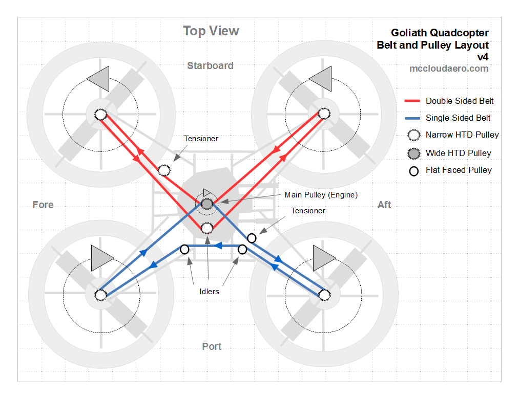
The drive system uses High Torque Drive (HTD) belts. These belts are made of neoprene rubber with fiberglass cords and are able to transfer more power per weight than roller chain and can also run at higher RPMs. To eliminate aerodynamic torque, the drive system rotates two propellers clockwise (CW) and two counter-clockwise (CCW). This is done by using two belts, one sided sided and the second double sided. The direction of rotation is changed by placing the outside of the double sided belt against the driving pulley.
Propellers
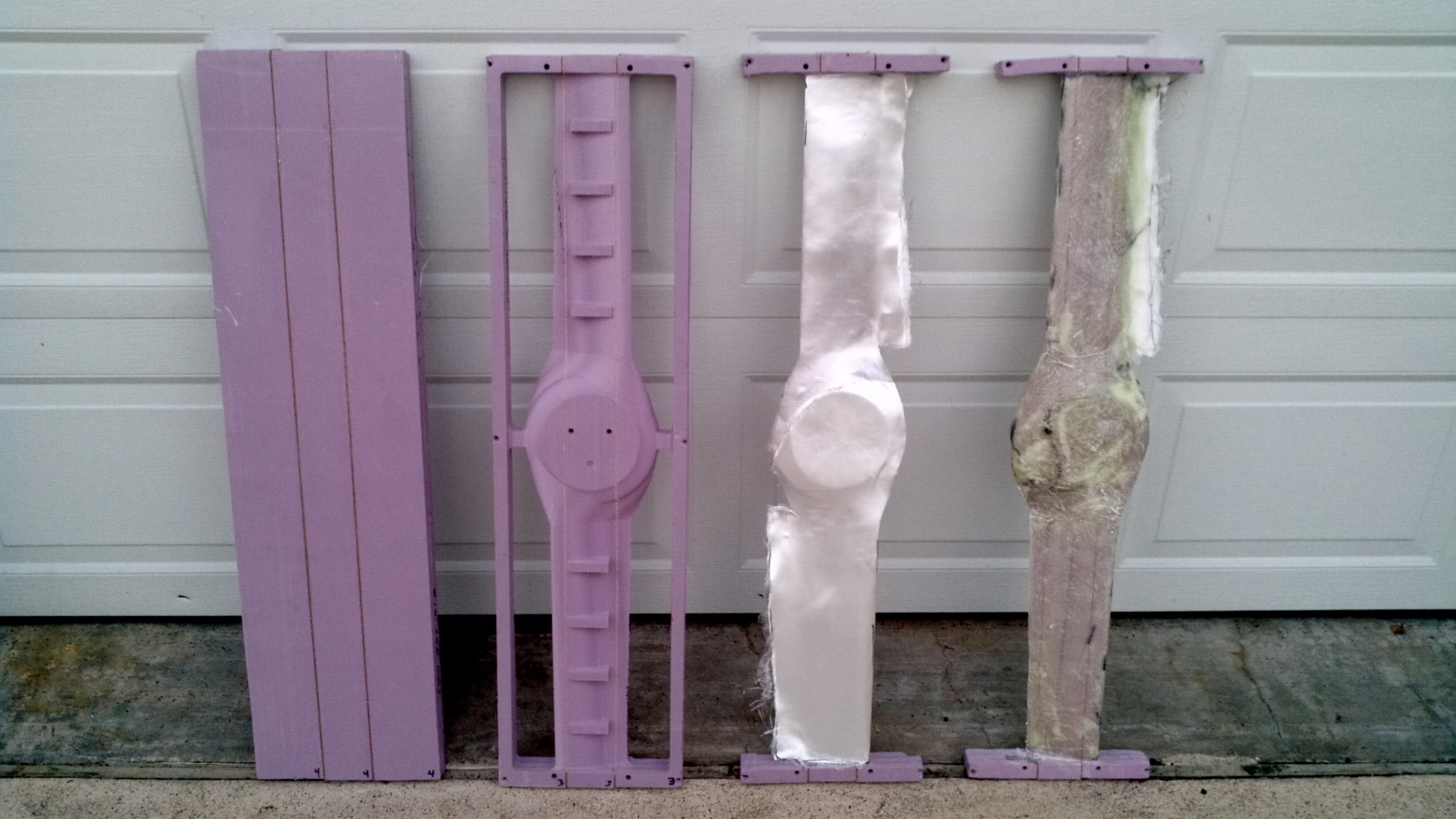
The propellers are fixed pitch propellers 36 inches in diameter. They are custom made, starting from a foam blank with birch stiffeners. The blanks are machined using a CNC router and then fiberglass and epoxy are laid up over the machined core. This process produces a propeller that can carry over 60 lbs while only weighing one and a quarter pounds.
Control
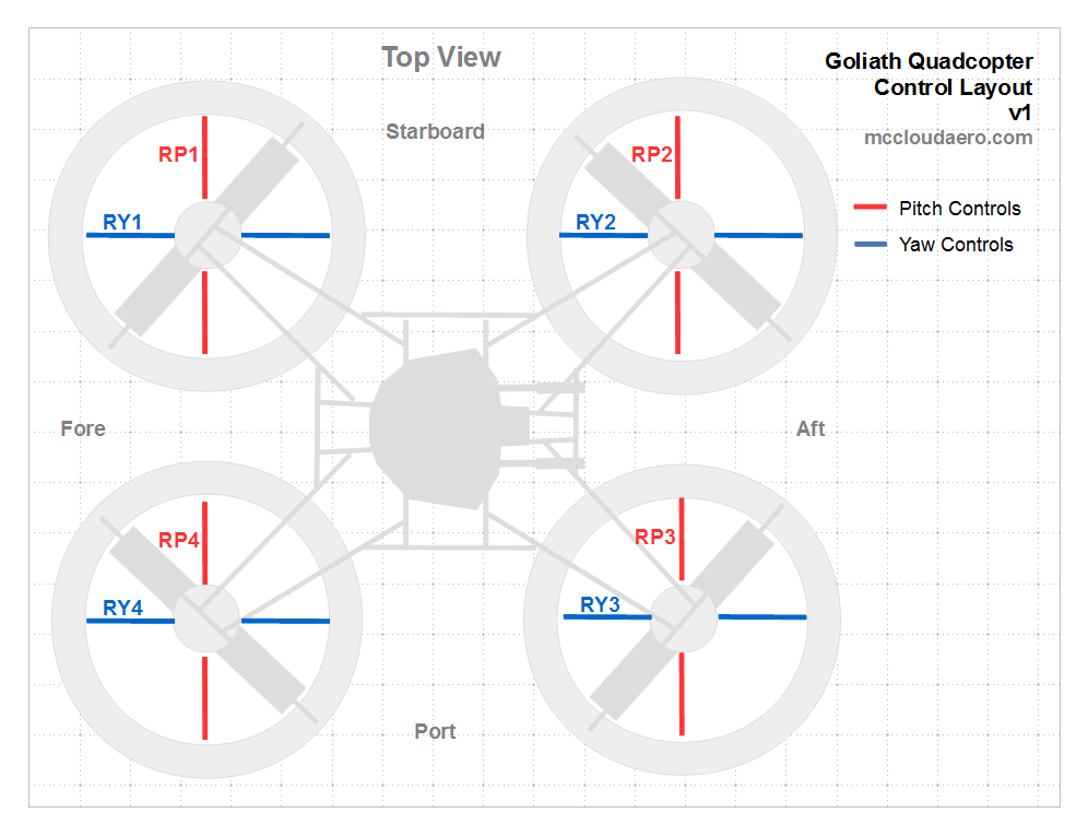
An electric quadcopter would traditionally maneuver by varying the speed of each propeller to control thrust. Since Goliath uses fixed pitch propellers and all the propellers turn at the same speed due to the belt drive, maneuvering will be done by control vanes similar to those used to steer hovercraft.
Frame
The frame is constructed using slotted galvanized angle, also known as Dexion, bolted together. While this is heavier than a steel tube or composite frame, the dexion is quickly assembled and can easily be reconfigured. At a later stage when the configuration is finalized the dexion could be swapped out for a lighter weight frame.
Exhaust
Each of the two exhaust pipes are built from Go-Kart hardware, which are easy to procure and inexpensive. The U-Build It Kits are easily assembled using a minimum of welding and highly customizable.
Electrical System
The electrical system is powered primarily from the alternator with the battery as a backup. The battery is 12V and designed for off-road vehicles, so it'll handle high vibration loads. The micro-controllers...
Read more »PROJECT LOGS
Test #15 and #16 Complete
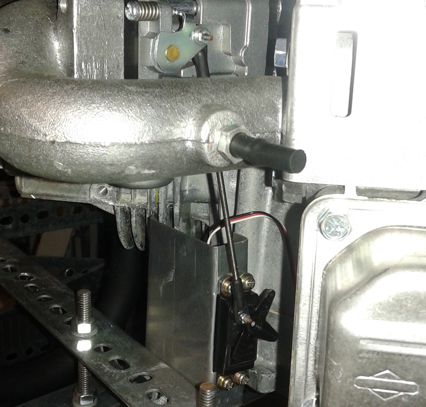
9 days ago • 2 commentsFinally got everything together to start testing again. I'll talk about the last couple of details needed to get Goliath ready after the video. The tests had some hiccups, (nothing was damaged) but it looks like the wider belts are working out better.One of the last things needed was new belt guards for the new frame dimensions. I cut a new set, making them 2 inches wide instead of 3 inches. This was because the rotors needed to be placed one notch closer to the engine, leaving a little less room for the belt guard. The second change was to add an extra fold to increase the stiffness.The new belt guard is on the left and the old one is one the right. Below you can see the tab made with the extra fold to add stiffness.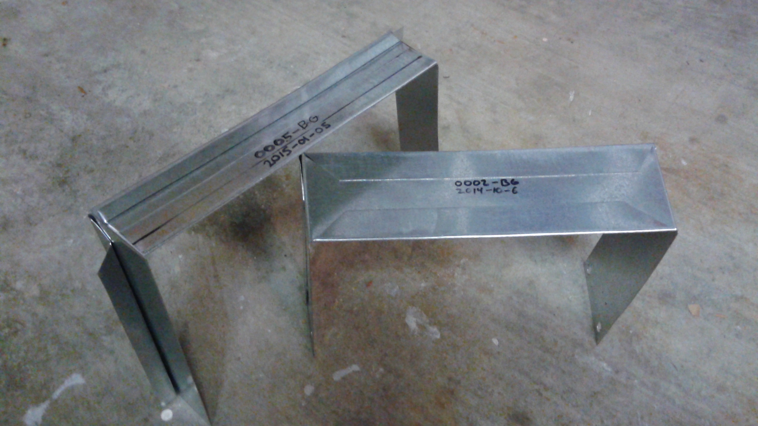 Next, the throttle servo had to be redone. Previously when the servo was mounted, I had to reverse the servo direction on the RC transmitter. This time I mounted the servo with the linkage on the opposite side of the servo so the controls didn't have to be reversed.
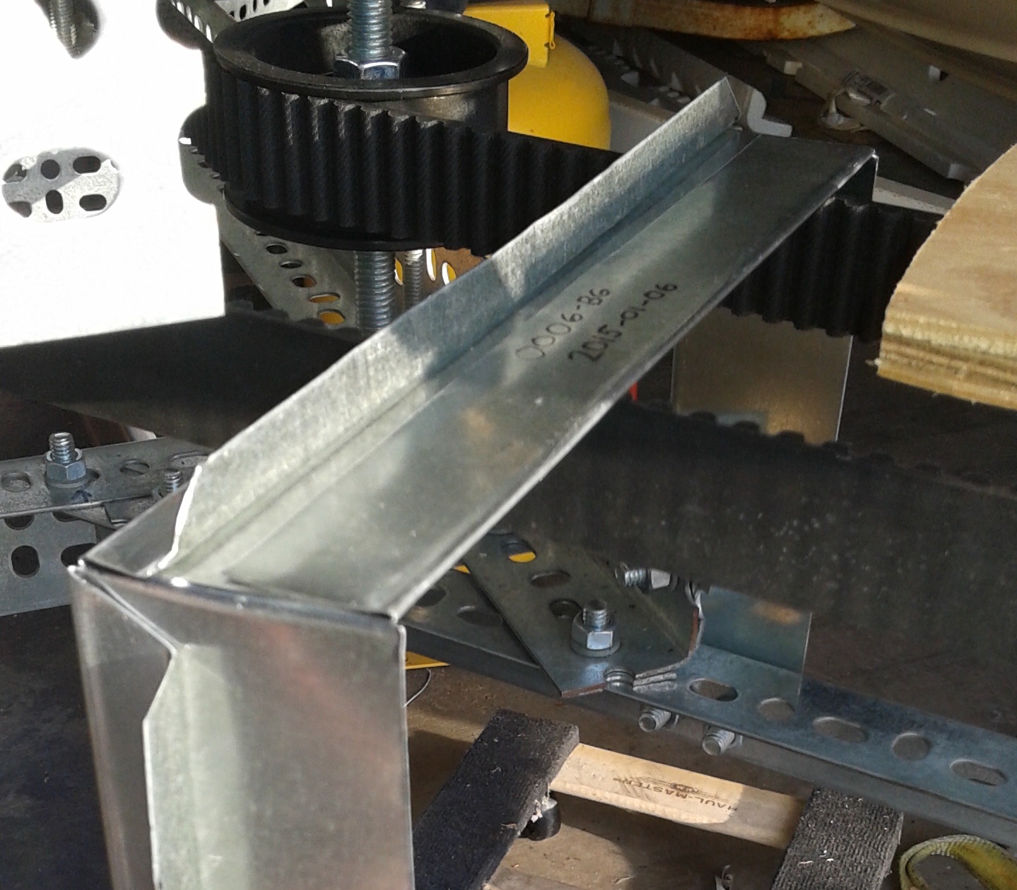
 With that done it was time to get back to testing.So the first test was the one with the hiccups. Since I was using the test props, I figured I wouldn't really need the guy lines to keep Goliath from twisting. The starter obviously provides a lot of torque and caused the vehicle to twist and rock back and forth. The second issue was that part way though the test was that the throttle servo got disconnected. When this happened the engine went to full throttle. Fortunately I was able to shut it off quickly. The culprit turned out to be a missing screw on the servo, (which was obviously missing in the above photo) and the control horn fell off during the test ( below).I quickly screwed the control horn back on and added the guy lines and did the next test (#16). This time things went well. The exhaust is rattling around and I need to tighten some more screws, but the tensioner is doing what its supposed to be doing now. Since I now the wider belts help, I'm going to place the order for the second belt.
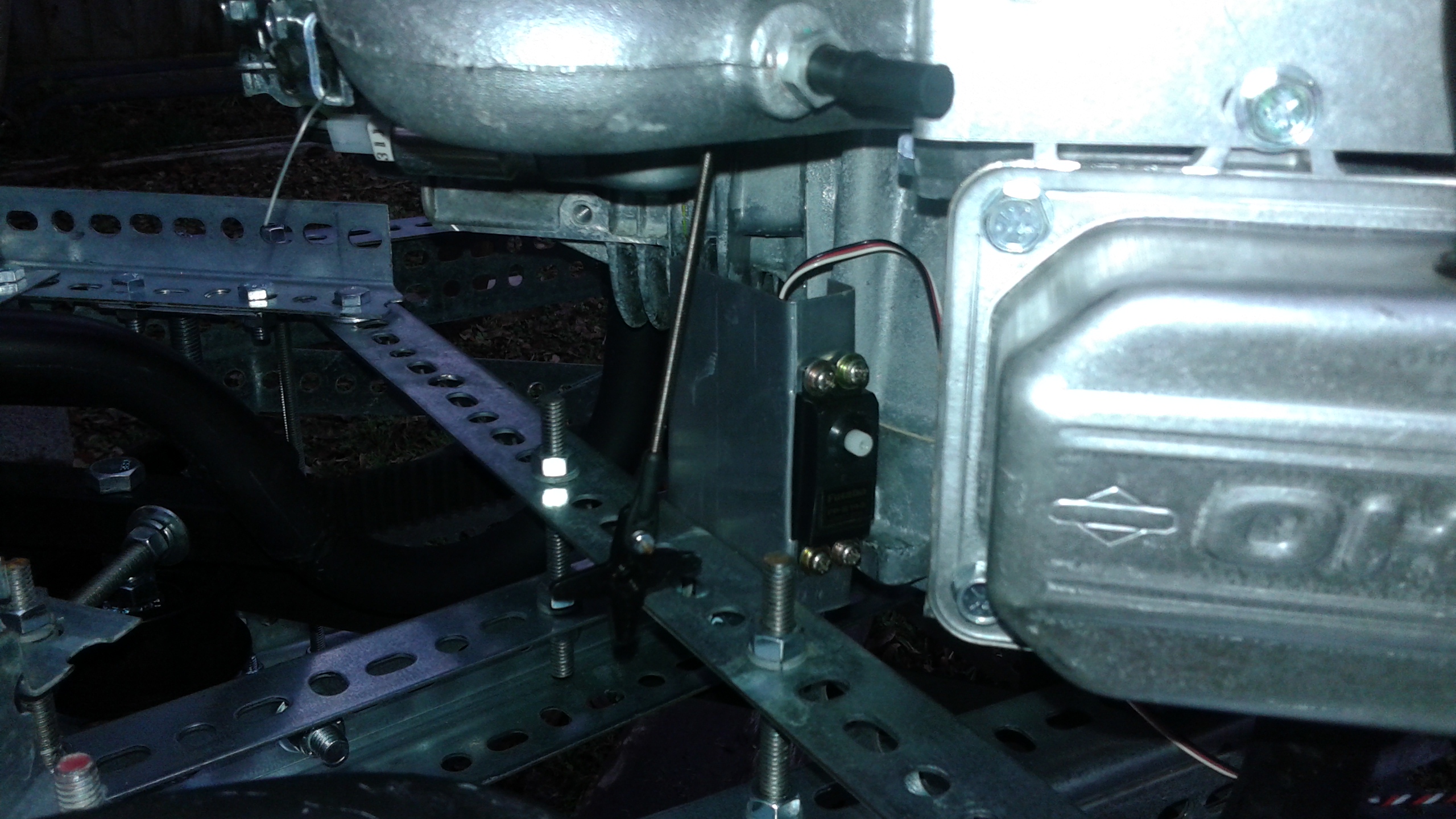 In the meantime I'll be checking things over, coming up with better mounts for the exhaust and likely the throttle servo as well. I'll also need to think about addressing a throttle linkage failure leading to the engine being stuck at full throttle. Seems like a spring or something else is needed to ensure that's not the case.
Firmware and Flight Stacks
16 days ago • 0 commentsWith the days shorter and the weather colder, I've had some time inside to dedicate towards figuring out the firmware. Early in the project I'd settled on the pixhawk (PX4) controller running the Ardupilot software. My goal was to modify the Ardupilot software to handle Goliath's unique control system. This seemed like a possible path since it had been done previously for the single and co-axial copter.Now that I've had some time to learn the details of the hardware and related software I have a better understanding of the system and my options. To start with, there is the PX4 hardware. The hardware runs a Real Time Operating System (RTOS) called NuttX. The autopilot software, called a Flight Stack, which actually controls the vehicle, is run by the operating system. What I didn't know before is that in addition to the Ardupilot Flight Stack, the Pixhawk has it's own Flight Stack that the user can choose.Ardupilot is open source and there is a large development community out there, the documentation for developers is somewhat lacking. Also as @J Groff pointed out, "it's quite a software thicket". It's doable (as demonstrated by the single and co-axial copters), but it'd be a significant amount of work to get the Ardupilot software modified for Goliath. The PX4 Flight Stack however has documentation on getting started as a developer and tutorials for developers to write their own Flight Stack. This seems like a better option, because I can get some simple code working to test Goliath out, and build up the code as Goliath matures. Once I get things nailed down, then I can work on integrating it with the rest of the PX4 Flight Stack.I've created a fork to the PX4 Firmware and I've started with some basic code based off the tutorials. For now it resides as seprate module, so the code I'm writing lives under /src/modules/goliath_simple. So far I just have some basic logic to start the controller in a startup state (MAIN_STATE_INIT), initialize some variables and look for a valid RC signal. When a RC signal is received then the controller will be switched to another mode. (for now MAIN_STATE_MANUAL). My next steps will be add some basic logic to deal with the ignition and starter relays and to shut off the relays if the RC signal is lost. (This code is primarily meant for the test stand for now, so I want to make sure thing shutdown if I can't communicate with it.)Things are still coming together on the actual hardware, hopefully just a few more items and it'll be back to the test stand to test out the changes.Belt Upgrade: Frame Reconfigured
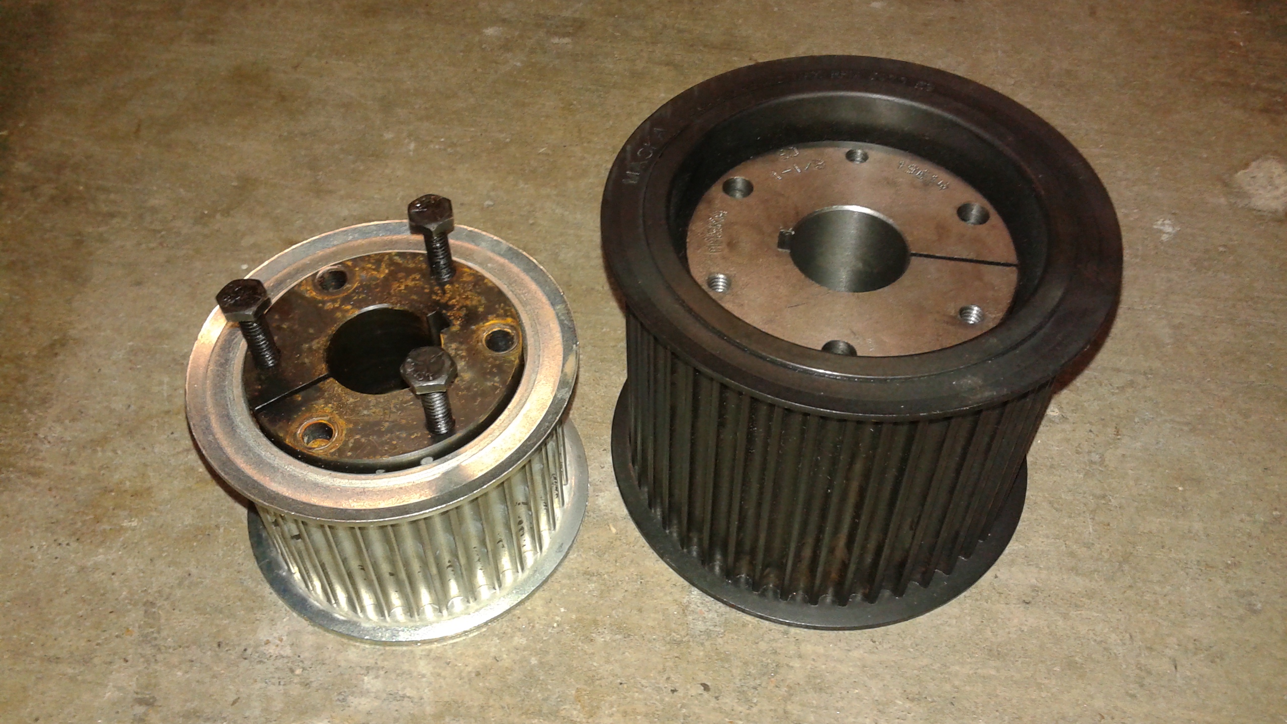
a month ago • 0 commentsCurrently I'm working on upgrading the belts on Goliath from 20 mm to 30 mm wide. Most of the hardware arrived a couple of weeks ago and I've been working on getting things installed. Below are the new and old prop pulleys with the ball bearing bushing. Both pulleys take SH Quick Disconnect (QD) Bushings, so I can reuse the same bushing.HTD 8mm pitch pulleys come in standard widths of 20, 30, 50 and 85 mm. Since the center pulley needs to accommodate two belts, the center pulley needed to be 85 mm wide. Below is the old and new center pulley with bushings. The new pulley required a bigger SD size bushing so a new bushing was needed.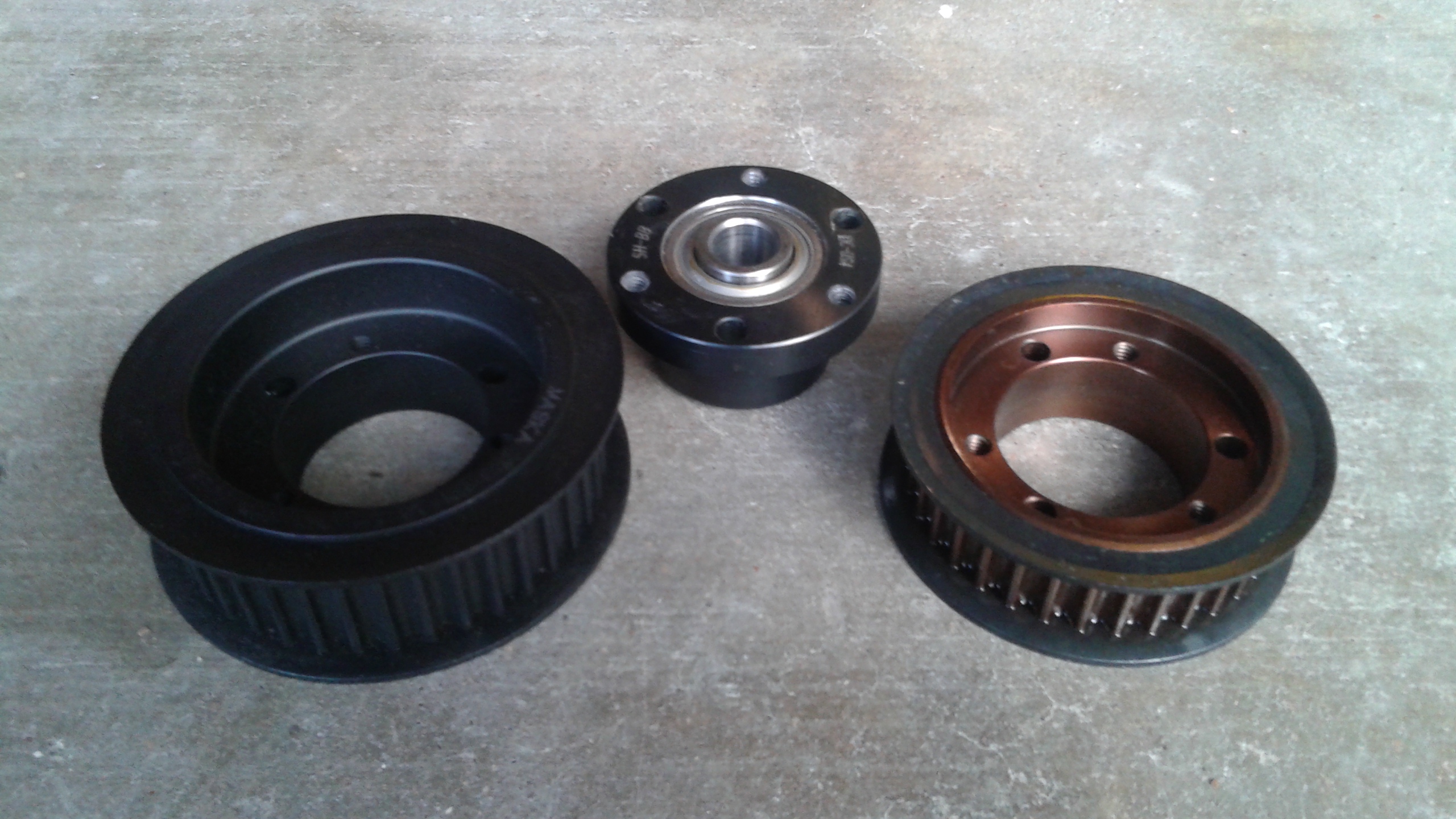
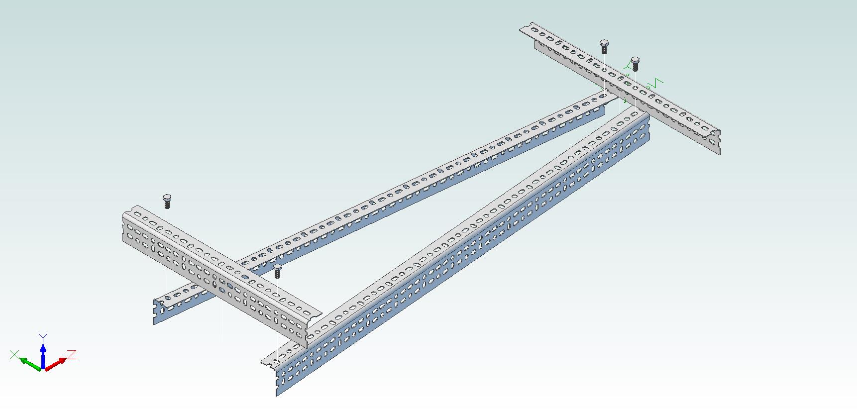
 A critical difference between the two pulleys is that for the the new pulley, the bushing is recessed and the top of the pulley sits above the top of the bushing. This means that the upper belt is closer to the engine. This was an issue since there was barely enough room previously between the upper belt and the center beams that the engine sits on top off. To make room, the engine had to be removed and the wide slotted angle replaced with narrow slotted angle.I was concerned that the narrow slotted angle wouldn't be stiff enough so I bolted a second narrow slotted angle to it to form a c-channel. To save some weight, the second piece only covers the primary span and none of the all thread runs through it. This means I can remove it easily if it proves to be unnecessary.
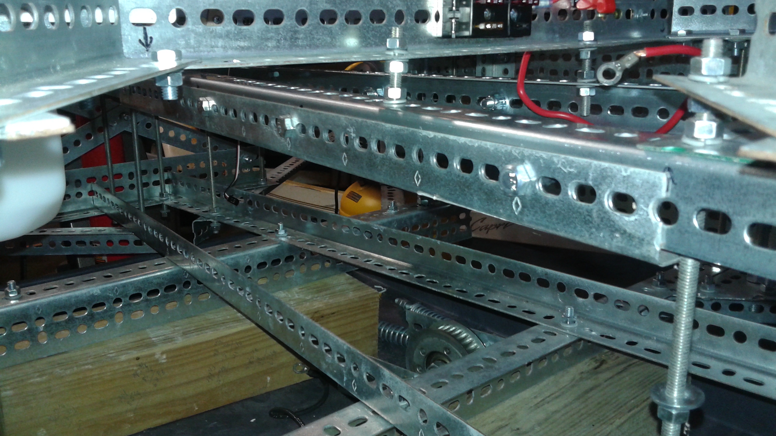 Next, the top of the center pulley had to be aligned with the rotor pulleys for the upper belt. The center beams already sat 1" below the top of the frame, but it had to be lowered another 3/4" so that the the pulleys were lined up. This part was a lot easier to do with the all thread construction. However the the cross beam that sits underneath the cylinder covers was in the way. It was a wide slotted angle piece, but after lowering the engine, there wasn't clearance for a narrow slotted angle. The solution was to flip the narrow angle over so that it pointed downwards.
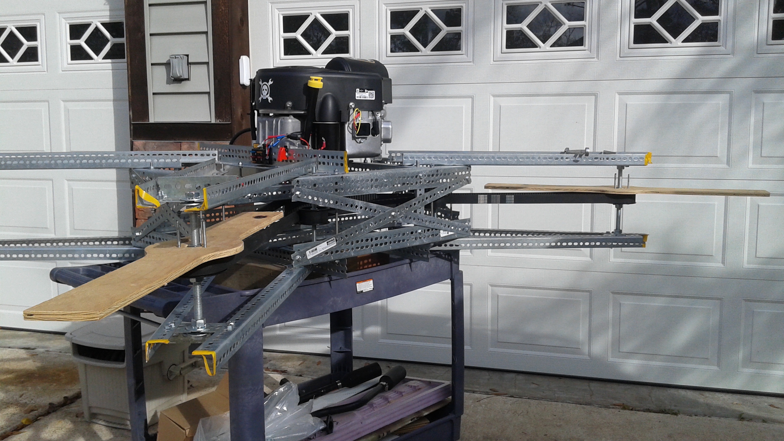
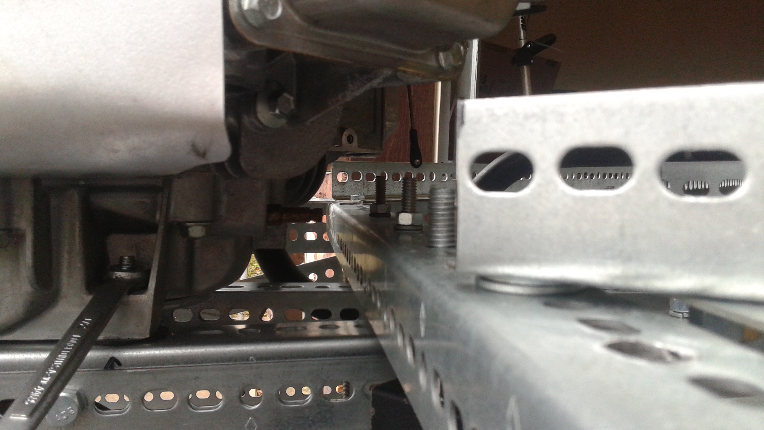 With the upper portion of the frame completed, the remaining modification was to make the whole frame taller to fit the center pulley between the cross members. This meant increasing the space between the decks about 1". While I had left some excess length in the all-thread to allow the frame to be expanded like this, it was somewhat fortuitous that I chose the length I did because it was just barely enough.As you can see, there isn't much excess room. Here's another shot to give you an idea of how Goliath as a whole looks now with one of the belts installed.
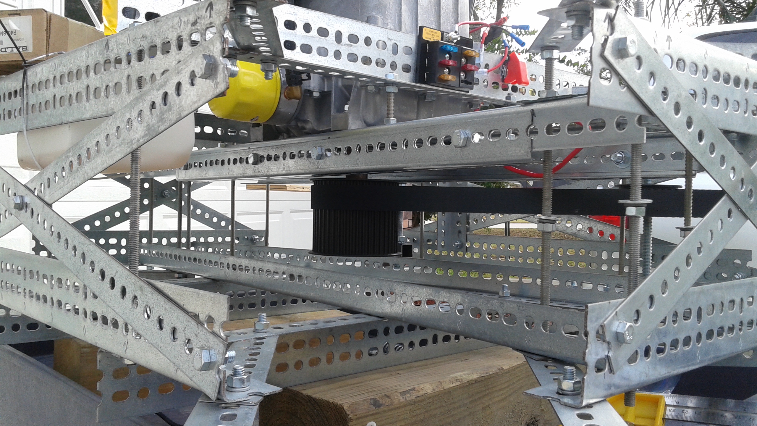 I think the changes to the frame are complete. The next steps are adjusting the pulley layout to account for the larger diameter pulleys and placing the tensioner on the slack side of the belt.
BUILD INSTRUCTIONS
THINK BEFORE YOU START
BUILDING THE COMPOSITES
- Propellers
- Ducts
- Control Surfaces
BUILDING THE FRAME
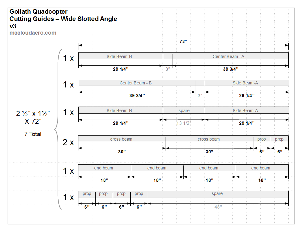
A) Cut the Frame Pieces
- 4× Center Beams ( 2 1/2" x 1 1/2" x 39 3/4")
- 4× Side Beams ( 2 1/2" x 1 1/2" x 29 1/4" )
- 4× Cross Beams ( 2 1/2" x 1 1/2" x 30" )
- 4× End Beams ( 2 1/2" x 1 1/2" x 18" )
- 8× Outer Prop Supports ( 1 1/2" x 1 1/2" x 30 3/4" )
- 4× Inner Prop Supports - Fore ( 1 1/2" x 1 1/2" x 28 1/4" )
- 4× Inner Prop Supports - Aft ( 1 1/2" x 1 1/2" x 32 1/4" )
- 8× Shaft Mounts - ( 2 1/2" x 1 1/2" x 6")
- 4× End Cross Bars ( 1 1/2" x 1/16" x 18" )
- 4× Side Cross Bars ( 1 1/2" x 1/16" x 30" )
- 1× Battery Plate ( 2 3/4" x 1/16" x 11 1/4" )
B) Assemble the Top and Bottom Decks
C) Join the Top and Bottom Decks